
Quick Navigation
- 1. A DRC-Clean Board Can Still Have Routing Problems
- 2. Why These Errors Are Hard to Catch in Standard DRC
- 3. High-Speed Routing Errors We Flag
- 4. Plane, Via, and Pad Errors We Flag
- 5. Auto-Correct Where Possible, Report Where Needed
- 6. What an AutoCuro Routing Report Shows
- 7. DRC Is Necessary, But It Is Not Enough
1. A DRC-Clean Board Can Still Have Routing Problems
A standard design rule check confirms that a board satisfies the rules currently configured in the CAD tool. It does not necessarily confirm that the completed route preserves signal timing, return-path continuity, or EMC-related risk margins.
We covered a version of this gap from the autorouter side in Can an Autorouter Tell If Your PCB Layout Is Good? — passing DRC answers a connectivity question, not an engineering-quality question. The same gap shows up after routing is complete, in places a standard rule set is not built to look:
- A DDR4 bus may be electrically connected but scattered across routing layers.
- A clock net may have an unintended stub.
- A differential pair may cross a void in its reference plane.
- A pad or via may sit over a copper void.
- A power plane may be split in a way that disrupts a signal's return path.
- A floating via may remain after routing edits.
None of these fail a typical DRC. All of them are worth a second look.
The important distinction
DRC confirms the rules you configured were followed. It does not confirm the completed route is electrically sound.
2. Why These Errors Are Hard to Catch in Standard DRC
Some of these checks can be implemented through custom rules in advanced EDA tools. The difficulty is less about whether the rule can exist, and more about what it takes to keep it useful in practice: layer-aware logic, net classification, and a visual review of the routed result across the whole board. In most workflows, these checks end up incomplete, inconsistently applied from board to board, or skipped entirely because stepping through every layer-via-net combination by hand does not scale.
| Standard DRC typically checks | Post-route review needs to assess |
|---|---|
| Clearance, width, connectivity, drill, basic pair constraints | Routing topology, via strategy, plane continuity, bus coherence, stubs, void crossings, and unintended artifacts |
| Individual geometry rule violations | The electrical meaning of the completed route |
| Whether a configured rule was violated | Whether the right rule existed in the first place, and whether the route still makes sense |
This is the gap the checks below are built to cover — not a replacement for DRC, but a layer of review that sits after it.
3. High-Speed Routing Errors We Flag
DDR4 buses routed inconsistently across layers
Members of a DDR4 bus can stay electrically connected while still ending up spread across multiple signal layers, with inconsistent layer changes or differing via counts between related signals in the same bus. Length matching alone does not capture this — route structure, layer transitions, and consistency across the bus matter too, and a mismatch here can show up as timing-margin loss on a bus that otherwise reports clean.
- Members of a DDR4 bus spread across multiple signal layers
- Excessive or inconsistent layer changes
- Different via counts across related signals in the same bus
- Routing structure that increases timing mismatch and makes manual review harder
Clock stubs and unnecessary branches
A clock net can be fully connected and within its length-matching target and still carry a branch or stub left over from routing or a later edit. Stubs like this are a known source of signal reflections, and the risk is more relevant on fast clocks and other timing-sensitive nets.
What was found: a stub on a clock net.
Why it matters: reflection and timing-margin risk on that net.
What AutoCuro does: corrects the stub directly on the routed board when the fix does not conflict with other constraints. When it cannot resolve the stub without affecting something else, it highlights the net for engineer review instead.
Differential pairs crossing reference-plane voids
Differential signaling does not remove the need for a controlled reference environment underneath the pair. When a pair crosses a void, split, or other discontinuity in its reference plane, the return path under that section can be impaired and the pair's effective impedance can shift. Depending on the net and the application, this can contribute to signal degradation or added EMI/EMC risk — it does not guarantee either outcome on its own, but it is exactly the kind of routing artifact that is easy to miss across a multi-layer board.
This is also the category of check our own testing found general-purpose LLMs could not perform reliably from board images — see Can LLMs Verify PCB Designs? The Results Were Mixed — since it requires actual geometric reasoning across layers, not a text description of what a layout looks like.
4. Plane, Via, and Pad Errors We Flag
Power-plane splits and interrupted return paths
Plane splits are not automatically a problem — many are intentional, separating power domains the way they should be separated. A split becomes a routing concern specifically when it creates a discontinuity directly under a signal path that depends on that plane for its return current, or when it blocks a clean return path entirely.
Pads over voids
A pad can look correctly placed in a top-level board view while the copper connection or reference plane underneath it is missing or interrupted. Depending on what that pad is doing, the result can be a weak electrical connection, a poor thermal path, or an unwanted discontinuity — the consequence depends on the pad's function, not on the presence of the void by itself.
Floating vias
A via can be left without its intended electrical connection after a few rounds of routing edits. In some designs this is a harmless leftover artifact; in others it points to incomplete routing cleanup, an unintended stub, or a stitching or return strategy that was never finished. The report flags the via and leaves the decision to the engineer — remove it, connect it, or keep it intentionally. The system does not assume every unusual object on the board is wrong.
5. Auto-Correct Where Possible, Report Where Needed
Not every finding is treated the same way. During routing, AutoCuro can correct certain issues directly on the routed board — for example, removing a clock stub when the fix does not conflict with other constraints on the board. When a fix depends on circuit intent, stack-up decisions, component placement, or a judgment call the tool is not positioned to make on its own, the issue is highlighted instead and left for the engineer to resolve.
| AutoCuro action | When it applies |
|---|---|
| Auto-correct | A routing fix can be applied directly on the routed board without creating a new conflict elsewhere |
| Flag for review | Resolution depends on circuit intent, stack-up, impedance targets, placement, or other engineering judgment |
| Document | The report records the issue, the affected nets and layers, supporting visuals, and its current status |
The goal is a clear boundary between what gets handled automatically and what still needs a human decision — not a tool that claims to resolve everything on its own.
6. What an AutoCuro Routing Report Shows
For every finding — corrected or flagged — the report includes:
- Issue category and severity
- Affected net or net group
- Relevant signal and reference-plane layers
- The specific location on the board
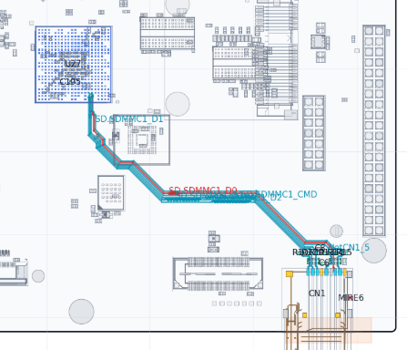
- An annotated image or layer overlay
- Why the geometry may matter
- Whether AutoCuro corrected it, or it is left open for review
A handful of examples below cover the categories described in this post: a full-board summary of flagged locations, a DDR4 bus issue, a clock stub, and a differential pair crossing a plane void.
7. DRC Is Necessary, But It Is Not Enough
DRC remains essential. A board that fails defined clearance, width, connectivity, drill, or manufacturability rules is not ready for fabrication, and nothing in this post changes that.
But a clean DRC is one checkpoint, not the finish line. The post-route questions are different: are DDR4 nets routed coherently? Do clocks carry stubs? Do differential pairs keep a usable reference path? Do vias, pads, and copper planes behave the way they are supposed to?
These checks flag routing patterns that are associated with signal degradation or EMI/EMC risk — they do not replace a full signal-integrity simulation or an engineer's sign-off, and they are not a guarantee that a board is fully clean. What they do is catch a category of issue that is tedious to find by manually stepping through layers, and put it in front of an engineer with enough context to act on it quickly.
Practical takeaway
DRC confirms a board followed its configured rules. AutoCuro's post-route checks look at what the routed result actually does — correcting what it safely can, and reporting the rest with the context needed to fix it.
Want to See a Post-Route Quality Report on a Real Board?
Request a technical demo to see an AutoCuro post-route quality report on a real PCB design.
Request Technical Demo View Case Studies
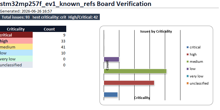
AutoCuro board verification dashboard summarizing total issues and criticality counts after routing review.
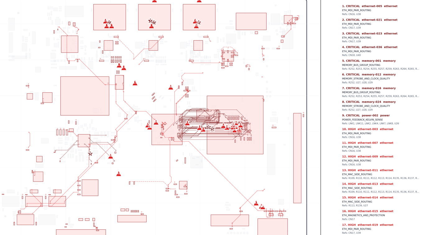
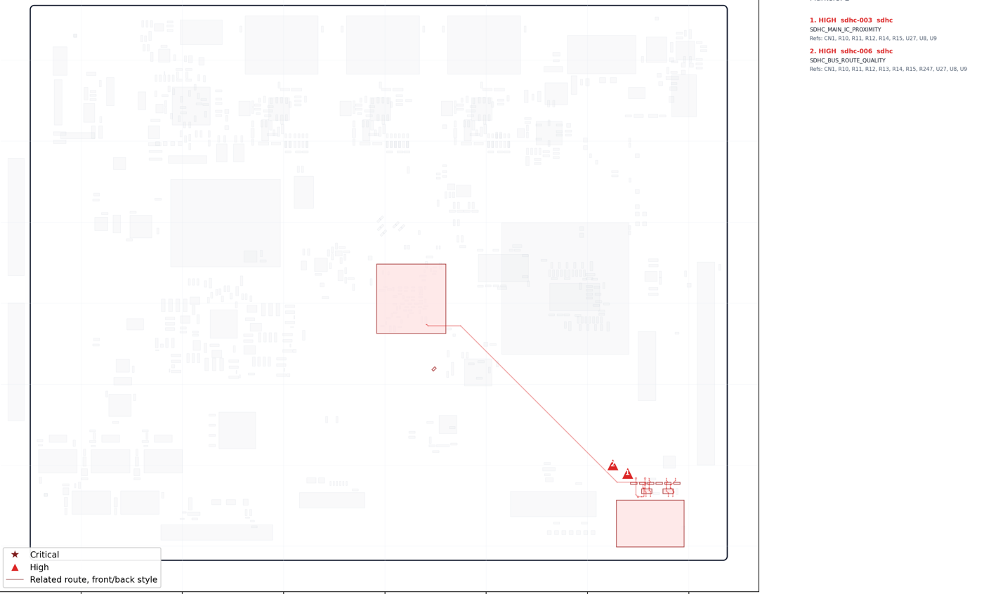
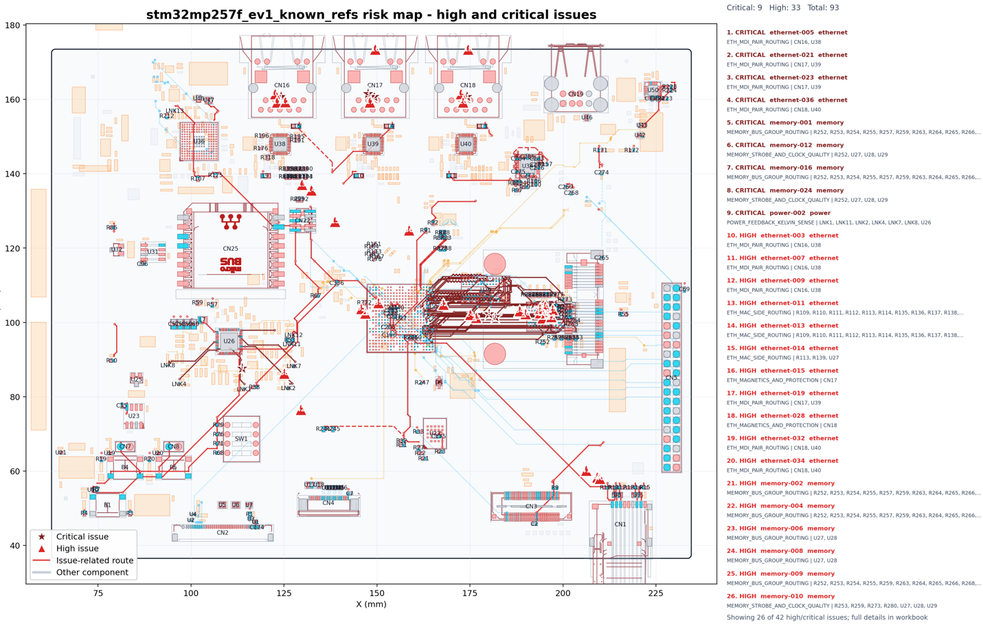
Full-board route review overlay highlighting critical and high-priority findings across the routed design.
Board-wide overlay showing flagged issue locations, affected nets, and routing context across the layout.
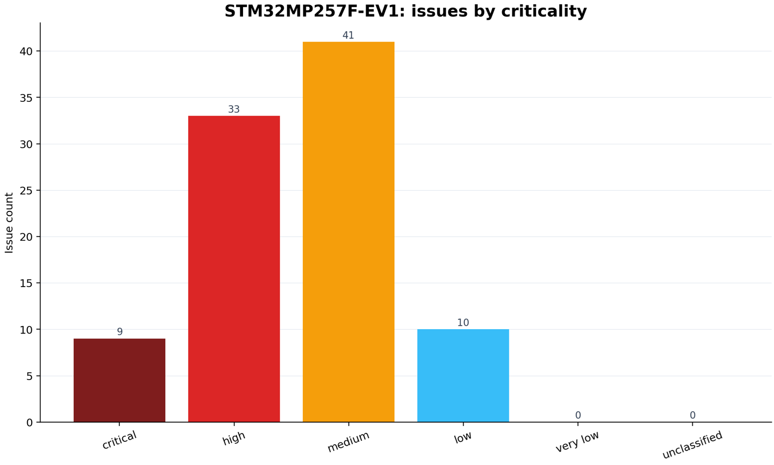
Issue count by criticality, showing how many findings were classified as critical, high, medium, and low.
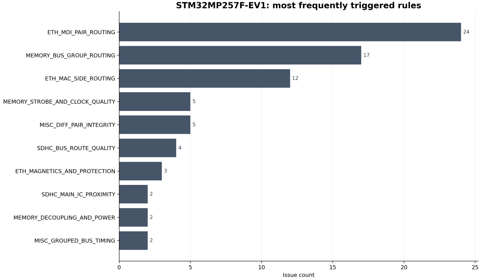
Most frequently triggered routing review rules, with memory, Ethernet, and SDHC checks among the top categories.
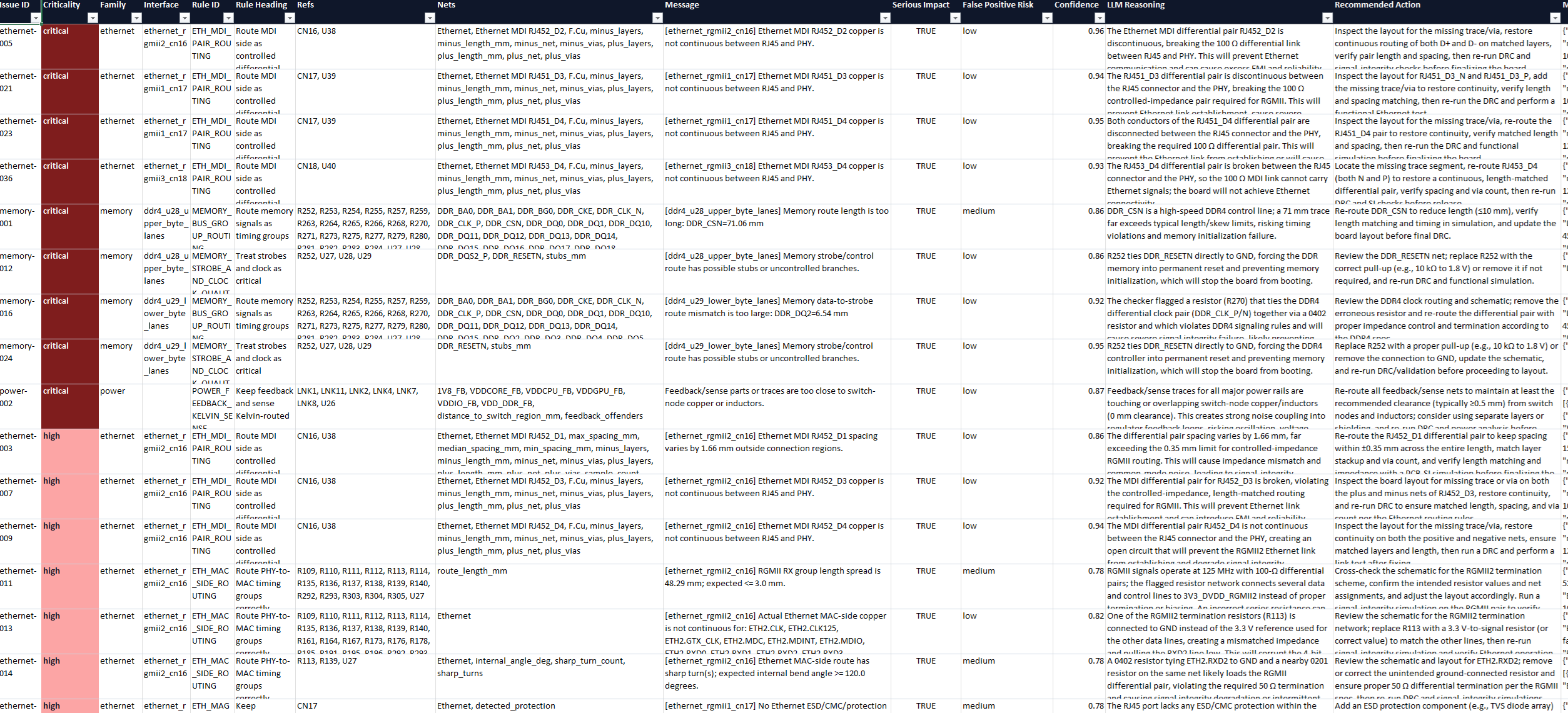
Issue detail table listing rule category, severity, affected nets, locations, and recommended engineering action.
Full-board report overlay tying issue markers back to the routed nets and physical board locations.